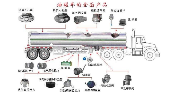
Aluminum alloy tank trucks refer to special vehicles for transporting liquid oils such as gasoline, diesel, kerosene, and lubricating oil. It is the most commonly used vehicle among liquid tank trucks. According to their functions, they are divided into oil tankers and refueling trucks. Oil tankers are used to transport liquid oils. It is mainly composed of oil tanks, filling ports, oil drain valves, manhole covers, oil hoses, grounding chains, etc.; and refueling trucks have the functions of mobile pumping stations in addition to the functions of oil tankers. He also added oil pumping systems, metering systems, and operating devices.
1.Tank body
The tank bodies of oil tank trucks are mostly welded with aluminum alloys. The two ends of the tank body are sealed by the heads, and the middle is an elliptical cross-section tank body. The tank body is equipped with partitions, longitudinal wave-breaking plates, transverse wave-breaking plates and corresponding supports. The upper part of the tank body is equipped with a protective frame 3, a manhole cover 4 and an overflow pipe 2. The lower part of the tank body is welded with a pipe body support 6 and a bottom valve seat hole. The wall thickness of the tank should be greater than 3.2 mm. The inner surface of the tank should be sandblasted first and then zinc-coated (or sprayed).
(1) Partition: When the capacity of the tank is not large, the entire container is used as a single chamber; if the capacity of the tank is large, the container needs to be divided into several independent single chambers by partitions, and each single chamber is equipped with a manhole cover and a bottom valve assembly.
Because when the vehicle is driving, there is a certain gap in the liquid tank or it is not full, and the liquid fluctuates back and forth and left and right in the container. If the capacity of the container is large, the kinetic energy of the fluctuation is large, and the change of the center of mass is also large, which will cause a drastic change in the vehicle axle load and seriously affect the stability of the vehicle. In particular, when the liquid tank semi-trailer car train is driving uphill, if the container is large and there is no partition, the liquid flows to the rear of the container, resulting in a significant reduction in the axle load of the traction vehicle drive shaft, reducing the passability of the car train, and the traction of the traction vehicle cannot be fully exerted. When driving downhill, the liquid flows to the front of the container, which also causes the axle load of the traction vehicle to change.
Dividing a large-capacity liquid tank into several single chambers can improve the above situation, and several different liquid goods can be transported on the same tank truck at the same time.
There is no uniform standard for the capacity of each single chamber of the tank body. It depends on the nature of the goods and the total capacity of the entire container. When the total capacity of the container is less than 20 m3, the capacity of each single chamber should be less than 4 m3.
(2) Wave-breaking board: In order to reduce the fluctuation of the liquid in the container during the driving of the vehicle, each single chamber of the tank body is generally equipped with a wave-breaking board. The longitudinal wave-breaking board 8 is arranged along the longitudinal axis of the vehicle to reduce the left and right fluctuation of the liquid in the container; the transverse wave-breaking board 9 is arranged along the cross-section of the vehicle to reduce the front and back fluctuation of the liquid in the container.
For the convenience of maintenance, a manhole with a diameter of not less than 550 mm is also opened on the transverse wave-breaking board 9. In order to improve the wave-proof effect of the transverse wave-breaking board, the manholes on two or more wave-breaking boards in the same single chamber should be staggered.
(3) Protection frame: The protection frame is located on the upper part of the tank body, and its height should be more than 50 mm higher than the top, so as to protect the upper devices such as the filling port and the safety valve; at the same time, it can collect rainwater in the protection frame or oil splashed during oil filling, and flow out through the overflow pipe at the front end of the tank body to avoid contaminating the entire outer surface of the tank body. The bottom valve seat hole at the bottom of the tank body can be connected to the oil discharge pipeline to form an oil transport vehicle, or it can be connected to the oil pump and connecting pipeline to form a refueling vehicle.
2.Manhole cover
The manhole cover is installed on the manhole cover hole on the upper part of the tank body. Most of them are fixed with bolts. The manhole cover is equipped with a filling port cover 7, a breathing valve 2, a connecting air pipe joint 1, a refueling duct 5, a full alarm and an observation hole. The manhole cover is usually not opened. Only when inspecting the interior, the fastening bolts are removed and the manhole cover is removed to facilitate workers to enter and exit for inspection or cleaning.
(1) Filling port: There are two filling port covers 7 on the manhole cover. Each filling port cover has its own hinge. An oil-resistant rubber gasket 6 is placed between the filling port and its cover. A pressure block is welded on the inside of each of the two filling port covers. When covering the filling port, the two pressure blocks are opposite but not touching each other. The pressure block is pressed by the pressure rod 9, and then the filling port cover is tightened to make it sealed and locked with a lock buckle 10 and a lock handle 11. The lock buckle and the lock handle are fixed together by an axis and hinged to the movable end of the pressure rod.
During use, if the rubber gasket is worn or cracked and causes oil leakage, the oil-resistant rubber gasket can be replaced. When the lock is worn and causes a loose seal, a steel plate that can eliminate the wear gap and ensure the compression of the rubber gasket can be welded to the bottom of the pressure rod at the contact point between the pressure rod 9 and the pressure block 8. The steel plate can also be repaired by changing the position of the hinge.
(2) Ventilation pipe: The vent pipe is also called the exhaust pipe. One end of the vent pipe is fixed to the front or rear end of the upper single chamber of the tank body with a hinge joint, and the other end is fixed to the manhole cover 4 with a hinge joint, so that the vent pipe connects the two ends of each single chamber and the manhole cover. The function of the vent pipe is to exhaust the air at the corners of the two ends of the single chamber when liquid is added to each single chamber of the container. It can also connect the two single chambers so that the two single chambers share a breathing valve. The vent pipe is generally made of a seamless steel pipe welded with a hinge joint.
(3) Refueling conduit: The refueling conduit is installed below the filling port. Its function is to shorten the distance between the filling port and the bottom of the tank. When the fuel enters the tank, the refueling conduit is submerged in the oil to avoid splashing during refueling, thereby reducing or eliminating the static electricity generated during refueling.
(4) Breathing valve: The breathing valve is also called a safety valve. The valve can automatically adjust the pressure in the container to keep the pressure within a certain range. This can not only protect the liquid tank, but also reduce the evaporation loss of volatile oil.
The breathing valve consists of an intake valve and an exhaust valve. The intake valve 2 and the exhaust valve 4 are two one-way valves installed in opposite directions. The intake valve has a small area affected by the gas, and the stiffness of its spring 7 is also small. The opening pressure is low, generally 4.9 kPa~9.8 kPa; the exhaust valve has a large area affected by the gas, and the stiffness of its spring 8 is also large. The opening pressure is high, generally 14.7 kPa~24.5 kPa. When the gas pressure in the container is lower than 4.9 kPa~9.8 kPa, the suction valve opens under the pressure difference between the inside and outside of the container, overcomes the elastic force of the spring 7, inhales part of the air, and raises the pressure in the container to the normal value, and the suction valve closes; when the gas pressure in the container exceeds 14.7 kPa~24.5 kPa due to the increase of volatilization or the increase of temperature, the exhaust valve opens under the pressure difference between the inside and outside of the container, overcomes the elastic force of the spring 8, discharges part of the gas in the container, and reduces the pressure in the container to the normal value.
The valve body 1 of the breathing valve is made of nickel-cadmium stainless steel, and the other parts are also made of stainless acid-resistant steel to prevent rust. Small and medium-sized oil tanks generally have one breathing valve for each single chamber, while large oil tanks have one breathing valve for each single chamber.
The suction pressure and exhaust pressure of the breathing valve are adjusted by adjusting nuts 9 and 10 respectively. The sealing ring 3 can be replaced if it is damaged or swollen. The copper wire mesh 5 can be cleaned or replaced when it is stained with oil to ensure its ventilation. The working condition of the breathing valve should be checked regularly to ensure that it works sensitively and reliably.
(5) Full alarm: The full alarm is also installed on the manhole cover. When the liquid level in the tank changes rapidly, the gas will sound through the exhaust pipe 2 through the double-tone whistle 3. When the liquid level reaches the rated height, the float 1 floats up with the liquid surface to block the exhaust pipe 2, and the whistle stops, which acts as a full alarm; when the liquid in the tank is emptied, the whistle also stops.
The bottom valve is a control valve for liquid discharge or suction into the tank. A bottom valve is installed at the bottom of each single chamber of the tank. The structural type of the bottom valve is related to the type of tank truck (such as oil tanker or refueling truck) and the cargo transported. The operation modes of the bottom valve include manual, starting, electric and hydraulic. Manual operation is simple and reliable, and this operation mode is mostly selected. The bottom of the tank is also equipped with a sedimentation tank and a drain valve. The drain valve can be opened from time to time according to the situation to release the dirt deposited in the sedimentation tank.
(1) Manual ball valve: Manual ball valve is a control valve commonly used in liquid tank trucks. There are two types of ball valves: two-way ball valves and three-way ball valves. For example, the drain valve of an oil tanker and various operations of a refueling truck are achieved by opening or closing ball valves at different locations. Most refueling trucks or oil tankers use aluminum alloy ball valves. There is a through hole in the middle of the ball 12, which is installed in the space formed by the left and right valve bodies 5 and 11 through the sealing ring 1 and the support seat 4. The contact surface between the ball and the sealing rings at both ends forms the sealing surface of the ball valve. The back of the sealing ring is installed on the valve seat 2, and the butterfly spring 3 pushes the valve seat 2 to make the sealing ring 1 elastically contact with the ball. The compression of the contact surface can be adjusted automatically, eliminating the influence of temperature changes and deformation and wear of the sealing ring, improving the sealing of the valve, and is a relatively ideal structure. The handle 10 controls the ball 12 to rotate in the two support seats 4 and the sealing ring 1 through the valve stem 7. When the handle is parallel to the axis of the valve body flange, the ball hole is connected to the valve body aperture at both ends and is fully open; when the handle is perpendicular to the valve body flange axis, the ball blocks the valve body at both ends and the aperture is closed.
The handle of the ball valve can also be removed and replaced with a pneumatic or multiple ball valve linkage operating mechanism.
(2) Air-controlled bottom valve: Figure 7-14 shows an air-controlled bottom valve. The opening and closing of the bottom valve is controlled by a cylinder. When the bottom valve is closed, the valve plug 3 moves downward under the action of the spring 2, and is pressed on the valve body 5 through the sealing ring 4, and is sealed under the action of the spring force and liquid pressure; when the bottom valve is opened, the compressed gas enters the lower chamber of the piston 9, pushing the piston upward, and the piston pushes the piston rod 8, valve stem 6, and valve plug 3 to overcome the action of the spring 2 and the liquid, so that the valve plug 3 and the valve body 5 have a certain opening, and the bottom valve is opened, and the liquid can pass through the bottom valve. When the air control system fails, the screw 13 can be turned to push the piston rod 8 upward to open the bottom valve.
(3) Foot valve with emergency valve: Foot valve with emergency valve structure. The normal opening or closing of the valve 6 of the foot valve is controlled by the foot valve operating hand wheel 1 set on the top of the tank body 2, and the hand wheel drives the universal joint
